what telescopes use lenses and mirrors to see into space.
Learning Objectives
By the end of this section, you will be able to:
- Outline the invention of a telescope.
- Describe the working of a telescope.
Telescopes are meant for viewing distant objects, producing an epitome that is larger than the image that can be seen with the unaided centre. Telescopes gather far more light than the centre, allowing dim objects to be observed with greater magnification and better resolution. Although Galileo is often credited with inventing the telescope, he really did not. What he did was more than of import. He constructed several early on telescopes, was the kickoff to study the heavens with them, and made monumental discoveries using them. Among these are the moons of Jupiter, the craters and mountains on the Moon, the details of sunspots, and the fact that the Galaxy is composed of vast numbers of individual stars.
Figure 1a shows a telescope fabricated of ii lenses, the convex objective and the concave eyepiece, the same construction used by Galileo. Such an system produces an upright image and is used in spyglasses and opera glasses.
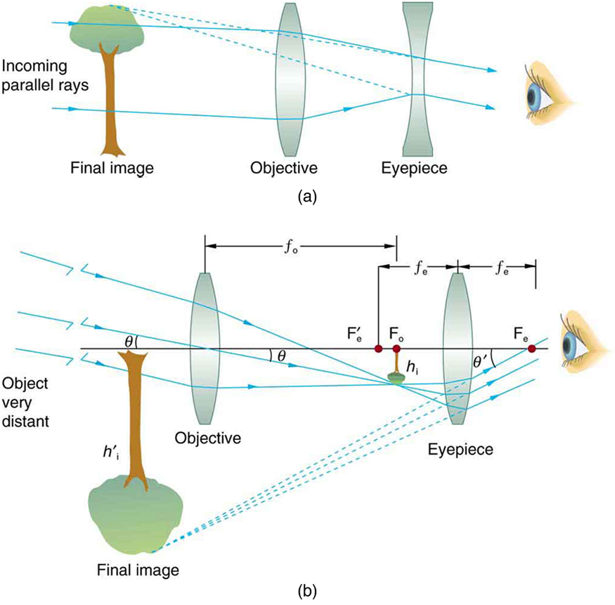
Effigy 1. (a) Galileo fabricated telescopes with a convex objective and a concave eyepiece. These produce an upright image and are used in spyglasses. (b) Virtually simple telescopes have two convex lenses. The objective forms a case 1 epitome that is the object for the eyepiece. The eyepiece forms a instance ii final image that is magnified.
The nearly common two-lens telescope, like the unproblematic microscope, uses two convex lenses and is shown in Figure 1b. The object is so far away from the telescope that it is substantially at infinity compared with the focal lengths of the lenses (d o ≈ ∞). The beginning image is thus produced at d i =f o, every bit shown in the figure. To prove this, notation that
[latex]\displaystyle\frac{1}{d_{\text{i}}}=\frac{1}{f_{\text{o}}}-\frac{1}{d_{\text{o}}}=\frac{i}{f_{\text{o}}}-\frac{ane}{\infty}\\[/latex]
Because [latex]\frac{1}{\infty}=0\\[/latex], this simplifies to [latex]\frac{1}{d_{\text{i}}}=\frac{1}{f_{\text{o}}}\\[/latex], which implies that d i =f o, every bit claimed. It is true that for any distant object and any lens or mirror, the image is at the focal length.
The first paradigm formed by a telescope objective every bit seen in Effigy 1b volition non be large compared with what yous might see past looking at the object direct. For case, the spot formed by sunlight focused on a piece of newspaper by a magnifying glass is the paradigm of the Sun, and it is small. The telescope eyepiece (like the microscope eyepiece) magnifies this starting time image. The distance between the eyepiece and the objective lens is made slightly less than the sum of their focal lengths so that the first epitome is closer to the eyepiece than its focal length. That is, d o′ is less than f e, then the eyepiece forms a case 2 epitome that is large and to the left for like shooting fish in a barrel viewing. If the angle subtended by an object as viewed past the unaided heart is θ, and the angle subtended past the telescope image is θ′, and so the angular magnification M is defined to exist their ratio. That is, [latex]Thousand=\frac{\theta^{\prime number}}{\theta}\\[/latex]. It can be shown that the angular magnification of a telescope is related to the focal lengths of the objective and eyepiece; and is given past
[latex]\displaystyle{M}=\frac{\theta^{\prime}}{\theta}=-\frac{f_{\text{o}}}{f_{\text{eastward}}}\\[/latex]
The minus sign indicates the image is inverted. To obtain the greatest athwart magnification, information technology is all-time to accept a long focal length objective and a short focal length eyepiece. The greater the athwart magnification M, the larger an object will appear when viewed through a telescope, making more details visible. Limits to observable details are imposed by many factors, including lens quality and atmospheric disturbance.
The image in most telescopes is inverted, which is unimportant for observing the stars simply a existent problem for other applications, such as telescopes on ships or telescopic gun sights. If an upright epitome is needed, Galileo's organization in Figure 1a tin can be used. But a more than common arrangement is to apply a third convex lens as an eyepiece, increasing the altitude between the first ii and inverting the prototype once over again every bit seen in Effigy 2.
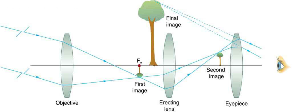
Figure ii. This arrangement of three lenses in a telescope produces an upright terminal image. The outset two lenses are far plenty apart that the second lens inverts the image of the showtime one more time. The third lens acts as a magnifier and keeps the image upright and in a location that is easy to view.
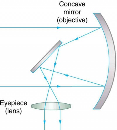
Figure 3. A 2-element telescope equanimous of a mirror as the objective and a lens for the eyepiece is shown. This telescope forms an image in the same way every bit the 2-convex-lens telescope already discussed, but it does not suffer from chromatic aberrations. Such telescopes can gather more calorie-free, since larger mirrors than lenses tin be constructed.
A telescope can also be made with a concave mirror as its first element or objective, since a concave mirror acts like a convex lens as seen in Figure 3. Flat mirrors are ofttimes employed in optical instruments to make them more compact or to transport light to cameras and other sensing devices. There are many advantages to using mirrors rather than lenses for telescope objectives. Mirrors can be constructed much larger than lenses and tin can, thus, gather big amounts of light, equally needed to view distant galaxies, for example. Large and relatively apartment mirrors have very long focal lengths, so that peachy athwart magnification is possible.
Telescopes, like microscopes, tin utilize a range of frequencies from the electromagnetic spectrum. Effigy 4a shows the Australia Telescope Compact Array, which uses six 22-m antennas for mapping the southern skies using radio waves. Figure 4b shows the focusing of x rays on the Chandra Ten-ray Observatory—a satellite orbiting globe since 1999 and looking at loftier temperature events equally exploding stars, quasars, and black holes. X rays, with much more than free energy and shorter wavelengths than RF and calorie-free, are mainly absorbed and non reflected when incident perpendicular to the medium. But they can be reflected when incident at pocket-size glancing angles, much like a rock volition skip on a lake if thrown at a small angle. The mirrors for the Chandra consist of a long barrelled pathway and four pairs of mirrors to focus the rays at a point ten meters away from the entrance. The mirrors are extremely smooth and consist of a drinking glass ceramic base of operations with a thin coating of metal (iridium). Four pairs of precision manufactured mirrors are exquisitely shaped and aligned then that x rays ricochet off the mirrors like bullets off a wall, focusing on a spot.
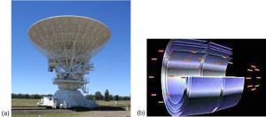
Figure four. (a) The Commonwealth of australia Telescope Compact Array at Narrabri (500 km NW of Sydney). (credit: Ian Bailey) (b) The focusing of 10 rays on the Chandra Observatory, a satellite orbiting world. X rays ricochet off 4 pairs of mirrors forming a barrelled pathway leading to the focus point. (credit: NASA)
A current heady evolution is a collaborative effort involving 17 countries to construct a Foursquare Kilometre Array (SKA) of telescopes capable of covering from eighty MHz to 2 GHz. The initial phase of the project is the construction of the Australian Square Kilometre Assortment Pathfinder in Western Australia (come across Figure 5). The projection will utilise cutting-edge technologies such as adaptive optics in which the lens or mirror is synthetic from lots of carefully aligned tiny lenses and mirrors that can exist manipulated using computers. A range of rapidly changing distortions can be minimized by deforming or tilting the tiny lenses and mirrors. The utilise of adaptive optics in vision correction is a current area of research.

Figure 5. An artist's impression of the Australian Square Kilometre Array Pathfinder in Western Australia is displayed. (credit: SPDO, XILOSTUDIOS)
Section Summary
- Simple telescopes can be made with two lenses. They are used for viewing objects at large distances and apply the entire range of the electromagnetic spectrum.
- The angular magnification M for a telescope is given past [latex]M=\frac{\theta^{\prime}}{\theta }=-\frac{{f}_{\text{o}}}{{f}_{\text{e}}}\\[/latex], where θ is the angle subtended past an object viewed past the unaided eye, θ′ is the angle subtended past a magnified image, and f o and f e are the focal lengths of the objective and the eyepiece.
Conceptual Questions
- If you want your microscope or telescope to project a real image onto a screen, how would you lot alter the placement of the eyepiece relative to the objective?
Bug & Exercises
Unless otherwise stated, the lens-to-retina distance is 2.00 cm.
- What is the angular magnification of a telescope that has a 100 cm focal length objective and a ii.50 cm focal length eyepiece?
- Observe the altitude betwixt the objective and eyepiece lenses in the telescope in the above problem needed to produce a final image very far from the observer, where vision is most relaxed. Note that a telescope is normally used to view very distant objects.
- A large reflecting telescope has an objective mirror with a 10.0 yard radius of curvature. What angular magnification does information technology produce when a 3.00 chiliad focal length eyepiece is used?
- A small telescope has a concave mirror with a ii.00 grand radius of curvature for its objective. Its eyepiece is a 4.00 cm focal length lens. (a) What is the telescope's angular magnification? (b) What angle is subtended by a 25,000 km bore sunspot? (c) What is the bending of its telescopic image?
- A vii.5× binocular produces an angular magnification of −seven.50, interim like a telescope. (Mirrors are used to brand the image upright.) If the binoculars have objective lenses with a 75.0 cm focal length, what is the focal length of the eyepiece lenses?
- Construct Your Ain Trouble. Consider a telescope of the type used by Galileo, having a convex objective and a concave eyepiece as illustrated in Effigy 1a. Construct a trouble in which you calculate the location and size of the image produced. Amid the things to exist considered are the focal lengths of the lenses and their relative placements as well as the size and location of the object. Verify that the angular magnification is greater than one. That is, the angle subtended at the eye by the prototype is greater than the angle subtended by the object.
Glossary
adaptive eyes: optical technology in which computers adjust the lenses and mirrors in a device to correct for image distortions
angular magnification: a ratio related to the focal lengths of the objective and eyepiece and given equally [latex]1000=-\frac{{f}_{\text{o}}}{{f}_{\text{e}}}\\[/latex]
Selected Solutions to Problems & Exercises
ane. −twoscore.0
3. −1.67
5. +10.0 cm
pollardprionsprould1946.blogspot.com
Source: https://courses.lumenlearning.com/physics/chapter/26-5-telescopes/
0 Response to "what telescopes use lenses and mirrors to see into space."
Post a Comment